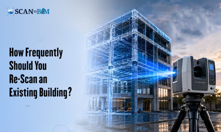


A Scan to BIM model can look complete in a 3D view and still contain dimensional inaccuracies, missing building elements, incorrect coordinates, or poorly structured data. These issues may remain unnoticed until the model is used for renovation planning, MEP coordination, quantity estimation, or construction documentation.
Quality assurance, therefore, must go beyond visual inspection. It should establish whether the delivered model accurately represents the scanned environment, meets the agreed modeling requirements, and can be used reliably within the intended project workflow.
Autodesk University’s guidance on Scan to BIM quality control highlights the importance of defining scope, acceptable deviations, model setup, and systematic verification rather than relying on visual judgment alone. (Autodesk University)
Whether you are reviewing an existing-building model or evaluating deliverables from a Scan to BIM Company, the following 12-point checklist can help architects, BIM managers, contractors, and project owners make informed acceptance decisions.
12 Things to Verify Before Accepting a Scan to BIM Model
- Point Cloud Registration and Source Data Quality
Before evaluating the model, confirm that the source point cloud is suitable for the intended modeling task. Multiple scans must be registered into a consistent dataset, with overlapping scan stations aligned correctly.
Review the registration report, residual errors, control-point checks, and any documented limitations. Look for duplicated surfaces, ghosting, noise, and gaps around important building elements.
Where dimensional accuracy is critical, verify the registered cloud against independent survey control or check measurements, rather than relying exclusively on the software’s registration statistics.
Acceptance check: Source files, registration results, control checks, and known data limitations are documented and approved.
- Coordinate System, Units and Orientation
A geometrically accurate model can still be of no use if it is positioned incorrectly. Verify that the point cloud and BIM model share the intended coordinate reference, orientation, elevation datum, and units.
Check the relationship between the project origin, internal origin, project base point, and shared coordinates where applicable. Confirm alignment at multiple locations, not just one convenient reference point.
Autodesk specifically documents cases where coordinate origins and linking methods cause point clouds to appear in the wrong position in Revit. (Autodesk)
Acceptance check: The model aligns with the approved survey coordinates and project references without unexplained translation, rotation, or elevation offsets.
- Dimensional Accuracy and Agreed Tolerances
Dimensional accuracy should be evaluated against an agreed tolerance, not a vague expectation that the model is “accurate.”
Check representative dimensions such as wall positions, floor-to-floor heights, slab thicknesses, structural grid spacing, opening sizes, and critical MEP elevations. Prioritize dimensions that influence design decisions, equipment installation, or construction interfaces.
The project should define its required Level of Accuracy (LOA) and verification method before modeling begins. LOA addresses dimensional fidelity, whereas Level of Development (LOD) describes the development and reliability of model elements; they are not interchangeable. (usibd.org)
Acceptance check: Measured deviations fall within the project-specific tolerances, and exceptions are recorded.
- Completeness of Building Elements
Compare the model systematically against the point cloud and the agreed scope of work. Confirm that all required architectural, structural, and MEP elements have been modeled.
Inspect walls, columns, beams, slabs, ceilings, doors, windows, stairs, ducts, pipes, cable trays, and other specified components. Pay particular attention to service spaces, ceiling voids, plant rooms, and partially concealed building elements.
Not every visible object needs to be modeled. The acceptance criteria must distinguish between required elements, optional detail, and excluded or inaccessible areas.
Acceptance check: Every required element and zone is accounted for, with omissions and inaccessible areas explicitly identified.
- Geometry and Representation of Existing Conditions
Verify whether the modeled geometry reflects the building’s actual condition rather than an idealized design.
Existing buildings may contain sloping walls, uneven floors, irregular columns, non-parallel surfaces, and construction deviations. Automatically regularizing these elements can create a clean-looking model that misrepresents the site.
Review plans, elevations, sections, and 3D views against the point cloud. Confirm that simplified geometry remains appropriate for the intended use and that significant deviations have not been concealed by modeling assumptions.
Acceptance check: Geometric simplifications are intentional, justified, and consistent with the agreed accuracy requirements.
- Openings, Connections and Critical Interfaces
Small modeling errors at interfaces can have disproportionate consequences. Review door and window openings, slab penetrations, structural connections, risers, shafts, and service openings.
For MEP-heavy projects, verify clearances and the relative positions of ducts, pipes, beams, ceilings, and equipment. Check whether openings align with the observed building fabric and whether modeled service routes reflect the captured conditions.
Where scans do not adequately reveal concealed connections or inaccessible spaces, the model should not imply certainty without supporting evidence.
Acceptance check: Critical interfaces are verified, discrepancies are documented, and unresolved conditions are flagged for investigation.
- Model Detail, LOD and Scope Compliance
A higher LOD does not automatically mean a better Scan to BIM deliverable. Excessive detail can increase file size and review effort without improving the model’s usefulness.
Check whether the agreed LOD is appropriate for the intended purpose, whether element categories meet the required representation, and whether non-geometric information is included where specified.
For example, a model intended for existing-condition documentation may require accurate wall positions and openings, while a model supporting fabrication or detailed installation planning may require more developed components and interface information.
Acceptance check: Model detail matches the approved scope, and LOD requirements are not confused with dimensional accuracy requirements.
- Architectural, Structural and MEP Coordination
Review discipline-specific models and their combined arrangement. Confirm that walls, slabs, beams, columns, ducts, pipes, and other components occupy consistent positions relative to the source scan.
Run suitable interference and clearance checks where coordination is part of the scope. Distinguish between genuine clashes in the existing building and errors introduced during modeling.
Remember that a clash-free model is not necessarily accurate: it may simply contain elements that have been incorrectly simplified or positioned to avoid interference.
Acceptance check: Required coordination checks are complete, critical discrepancies are resolved or logged, and the model remains faithful to the scanned conditions.
- Revit Model Structure and Element Classification
A model may match the point cloud geometrically but still be difficult to maintain if its elements are poorly structured. For a Point Cloud to Revit workflow, inspect whether walls, floors, doors, windows, structural members, and MEP components use appropriate native categories and families.
Check for excessive use of generic models, unnecessary in-place families, duplicated elements, incorrect host relationships, and inconsistent naming. Verify levels, grids, worksets, phases, and linked files against the project requirements.
Acceptance check: The model uses appropriate element categories, logical organization, and the required project settings.
- Model Performance and File Health
Large existing-building models can become difficult to navigate when they contain unnecessary geometry, excessive family complexity, redundant elements, or poorly managed views.
Open the native file and review warnings, model size, regeneration performance, linked datasets, and view responsiveness. Check for broken references, missing links, and unnecessary imports. Confirm that the model can be opened, saved, and reviewed in the agreed software version.
Autodesk’s quality-control guidance also emphasizes model setup, worksets, views, and final quality checks as part of a reliable delivery process. (Autodesk University)
Acceptance check: The file opens correctly, performs adequately, and contains no unresolved critical issues that prevent its intended use.
- Metadata, Naming and Deliverable Requirements
A technically sound model can create downstream problems if its information is incomplete or inconsistent.
Verify project identifiers, level names, element naming conventions, parameters, material information, and other required properties. Check whether existing, demolished, and proposed elements are distinguished correctly when the project requires phasing.
Review the delivery package against the agreed BIM Execution Plan (BEP), including the native model, linked files, drawings, schedules, exports, and any required documentation. Confirm that file naming, revisions, and version information are consistent.
Acceptance check: All required information is populated, naming conventions are followed, and the delivery package matches the agreed specification.
- Final Point Cloud Comparison and QA Documentation
The final acceptance decision should be supported by evidence that the model has been checked against the source data.
Overlay the model with the registered point cloud in representative plans, sections, elevations, and 3D views. Where suitable tools are available, use deviation analysis or color-coded comparison maps to identify areas where modeled surfaces depart from scanned points.
Document the checking method, sample locations, measured deviations, unresolved discrepancies, exclusions, and corrective actions. Review both the overall building and critical interfaces rather than relying on a few favorable screenshots.
Autodesk’s model-verification guidance describes comparing as-built models with scan data to identify discrepancies and make appropriate corrections. (Autodesk University)
Acceptance check: The final QA report records the verification results, outstanding issues, and formal approval status.
What Should a Scan to BIM Acceptance Report Include?
Before signing off, ensure that the following evidence is available:
| QA document | What it confirms |
| Source data and registration report | Scan provenance, alignment, and known limitations |
| Accuracy verification report | Measured deviations against agreed tolerances |
| Scope and completeness register | Required elements, zones, and exclusions |
| Model review report | Geometry, interfaces, coordination, and model health |
| Deliverable checklist | File formats, naming, metadata, and software compatibility |
| Issue and approval register | Open issues, corrective actions, and acceptance status |
The acceptance report should distinguish between verified results, sampled checks, and unverified assumptions. A completed checklist is evidence of a review process, not an automatic guarantee that every modeled element is correct.
Conclusion: Accept the Evidence, Not Just the Model
A reliable Scan to BIM deliverable combines dimensional accuracy, scope compliance, appropriate modeling detail, structured information, and verifiable quality control. No single screenshot, accuracy figure, or LOD designation can establish all these qualities.
For architects, contractors, and BIM managers, the best approach is to define acceptance criteria before work begins, review the model systematically, and require documented evidence of compliance before final sign-off.
Ultimately, a model’s value lies not in how detailed it looks, but in how confidently project teams can use it to make decisions about the real building.